What is network topology? Types, components and how it works
A network’s topology describes its physical or logical arrangement, shaping how data moves, where failures occur, and how the network scales.
It directly influences how infrastructure is designed and managed, with real-world networks combining multiple topologies to balance performance, resilience, cost and complexity.
This guide explains what network topology is, how physical and logical topology differ, the main topology types in practice, and the components that make them work.
Contents:
- What is network topology?
- What is the difference between physical and logical network topologies?
- Types of network topology
- How does network topology affect infrastructure?
What is network topology?
Network topology is the physical or logical arrangement of a network, including local, wide area and cloud environments.
It is represented by diagrams or maps showing how nodes physically or logically interconnect and how data flows between them, depending on what is being modelled:
- Physical topology: The physical infrastructure of the network, such as how devices connect locally through cables, network switches, and wireless LAN access points.
- Logical topology: How data is routed and forwarded across a network, including traffic flows, segmentation, and control mechanisms independent of physical layout.
Both physical and logical topology play a major role in how networks behave, influencing:
- Performance: How efficiently data moves between nodes.
- Scalability: How easily and cost-effectively the network can grow.
- Resilience: How well failures are absorbed through redundancy and failover.
- Complexity: How easy the network is to troubleshoot.
- Cost: Infrastructure and maintenance costs.
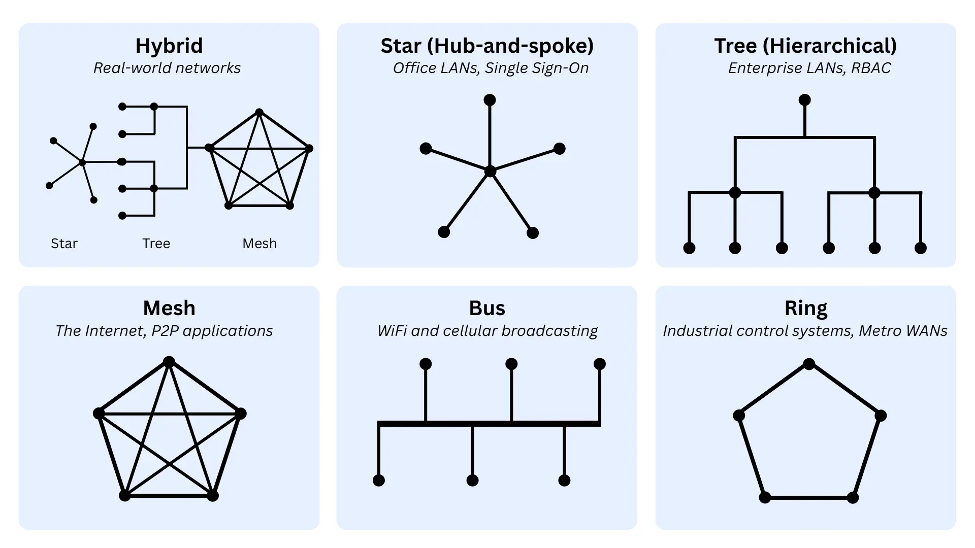
There are six major types of network topology, each with its own strengths and trade-offs. In practice, most networks consist of multiple interconnected segments, each with a topology suited to its role.
Network topology is not to be confused with topography, the geographical term describing physical terrain.
The concept of network topology also applies beyond IT networks. For example, the London Underground map is a topological representation of stations and routes, showing how locations connect rather than their exact geographic positions.
What is the difference between physical and logical network topologies?
Telecommunications networks can be understood through two distinct layers: the physical layer defines how the network is built, while the logical layer defines how it behaves.
Graphically, these are often shown separately (infrastructure vs data flow) or combined into layered diagrams, where logical behaviour is overlaid onto physical connections. A simple physical layout can support a far more complex logical structure.
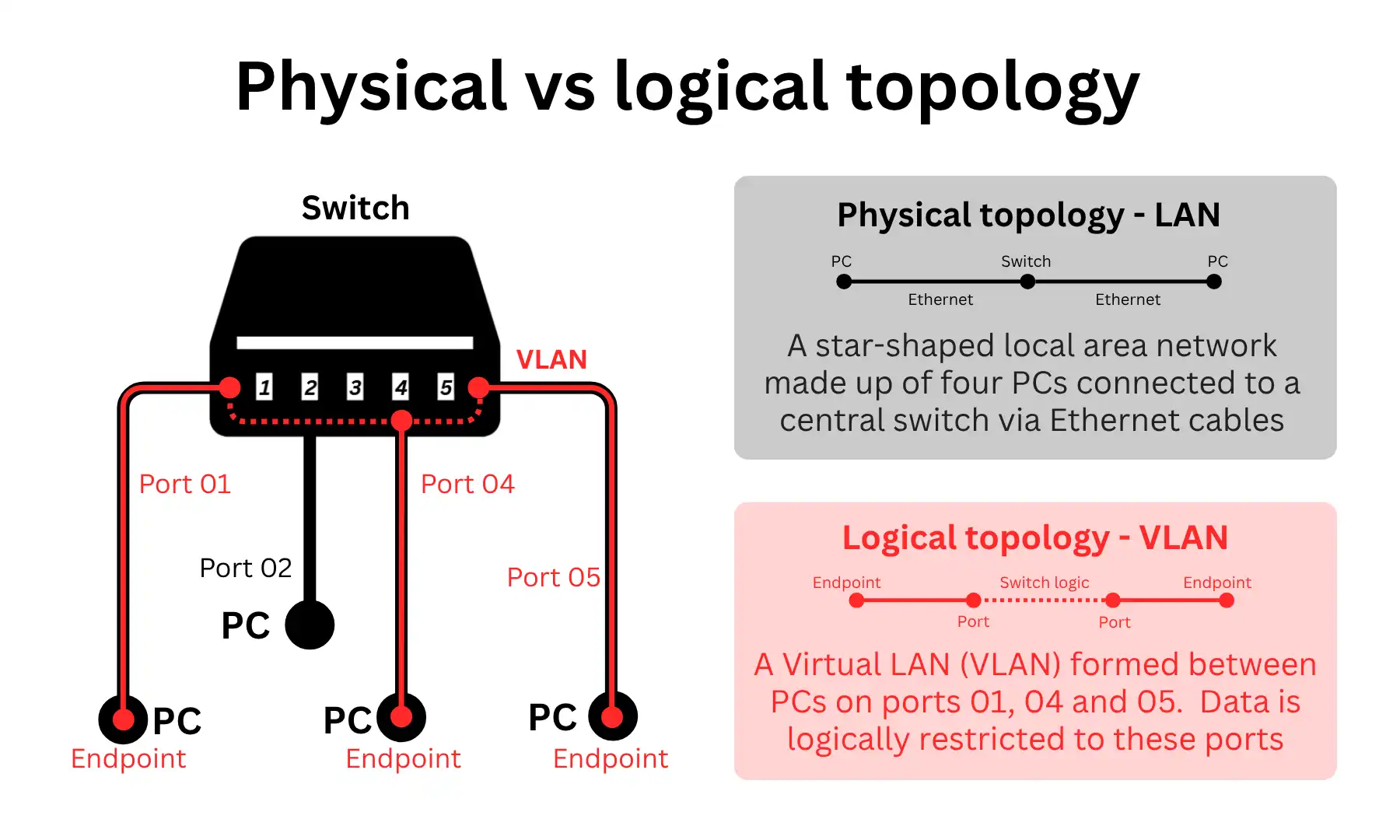
Understanding both layers is essential for designing, scaling, and troubleshooting networks effectively.
Physical network topology
Physical network topology describes the real-world layout of a network, showing how devices are connected through cables, ports, and hardware.
It is used to design, build, and maintain network infrastructure, and to identify where failures can occur if a link or device goes down.
Physical topology diagrams are made up of two core components:
- Connectors: The physical media that carry data between network points, such as Ethernet cables in local area networks, fibre optic and copper lines in wide area networks, and wireless signals in technologies like WiFi, cellular, and wireless leased lines.
- Nodes: The physical devices and locations that are interconnected, including switches, routers, firewalls, access points, servers, and endpoints in local networks, as well as sites, cabinets, exchanges, and data centres in wide area networks.
Logical network topology
Logical network topology describes how data moves through a network, independent of its physical wiring.
It is used to manage traffic flow, network segmentation, and performance and security enforcement.
Logical topology diagrams are made up of three core components:
Virtual data routes: How data flows between parts of the network, regardless of physical path, such as VLANs and IP subnets in local networks, VPN tunnels and MPLS paths in wide area networks, and SSIDs segmenting traffic in wireless networks.
Digital nodes: The logical entities that participate in the network, independent of physical hardware, including endpoints, virtual machines, containers, network interfaces, and logical gateways.
Traffic behaviour and control: How data is directed, prioritised, and secured, including routing and forwarding logic, segmentation policies, Quality of Service (QoS), and firewall or access control rules.
Types of network topology
Network topologies can be grouped into six categories, each with its own arrangement of nodes that gives it distinct strengths and weaknesses.
Some topologies make networks scalable, at the expense of performance and resilience. Others are resilient, but are costlier to build and maintain.
Their usefulness varies by scale (local/wide-area networks), medium of transfer (wired/wireless networks), and application (niche/general).
Below are details on each of the six types of topologies, and how they apply to both the physical and logical layers.
Hybrid topology
A hybrid topology combines multiple topology types, allowing networks to balance performance, scalability, resilience, complexity, and cost.
In practice, real-world networks are almost always hybrid: an aggregate of numerous sub-networks, each with its own topology, optimised for its use case.
Typical hybrid physical networks:
- Enterprise LANs: Combine star LANs, where devices connect to a local office switch. These connect into a tree-shaped WAN, where multiple office switches feed into a larger hierarchical campus or company network.
- WAN infrastructure: Often combines hub-and-spoke designs, where branch offices send most traffic to a central HQ or cloud hub for control and security. This is paired with a partial mesh, allowing critical sites to connect directly for faster and more resilient communication.
- Cloud regions: Sites are connected through wide-area, high-resilience backbone meshes. Data centres are interconnected through multiple paths, allowing traffic to be rerouted if a failure occurs.
Typical hybrid logical networks:
- SD-WAN overlays: Route traffic using a mix of hub-and-spoke for centralised breakouts and internet inspection. Mesh routing is used alongside this to support direct site-to-site traffic for important applications.
- Application architectures: Combine client–server models in which users interact with a central application. At the same time, applications communicate directly with each other through service-to-service interactions behind the scenes.
Star topology
In a star topology, a network has a central hub where all endpoints connect.
It centralises control at the hub, simplifying management and delivering strong performance characteristics, as all endpoints are one hop away from the hub and a maximum of two hops apart.
On the downside, it relies entirely on a central node, introducing a single point of failure and potential bottleneck unless redundancy or failover is introduced.
Typical star-shaped physical networks:
- Ethernet LANs: Local networks, such as office networks, where each device connects directly to a central switch via its own cable.
- Hub-and-spoke WANs: Branch sites connect to a central HQ or cloud hub rather than directly to each other.
Typical logical networks:
- Client-server communication: User devices send requests to a central application server and receive responses.
- Centralised application delivery: Users access services through a single front-end or gateway, such as a web server, load balancer, or virtual desktop platform, which brokers all application traffic.
Tree (hierarchical) topology
Tree (hierarchical) networks are made up of layers of sub-networks, with the upper-most node usually having overall control.
This arrangement makes the network highly scalable, as sub-networks can be added at any point in the hierarchy, which is already clearly structured with well-defined roles and traffic separation.
On the downside, it introduces dependency on higher layers and increases design complexity as the network expands.
Typical hierarchical physical networks:
- Enterprise LANs: Typically structured in layers (end devices connect to access switches, which connect to distribution switches, which connect to a high-speed core).
- Multi-building or campus LANs: Each building connects to a larger company-wide network through aggregation points.
Typical hierarchical logical networks:
- DNS resolution hierarchy: Queries are handled through a tiered system, moving from local resolvers to upstream authoritative servers in a structured, hierarchical chain.
- Local network segmentation: Devices are grouped into subnets or VLANs, which are then grouped into larger network zones.
Mesh topology
In a mesh network, nodes connect to multiple other nodes. In a full mesh, every node connects to every other node. This makes it highly resilient because nodes can communicate via alternative routes when a path or node fails.
The downside is that mesh arrangements lack centralised control and require managing a complex network of redundant paths.
Typical physical networks:
- The Internet: The global Internet is interconnected with multiple links, so traffic can always take alternative paths.
- WiFi mesh networks: Devices and wireless access points connect to multiple nearby points, extending coverage and routing traffic around weak or failed links.
Typical logical networks:
- SD-WAN, critical site connectivity: Automated, optimised WAN routing between critical sites leverages a mesh of redundant paths for maximum resilience.
- Peer-to-peer communication: Devices or systems connect directly to one another rather than through a central server.
Bus topology
A bus network is one in which all endpoints are connected via a shared backbone.
It is the simplest and most cost-efficient arrangement with minimal infrastructure requirements, but suffers from poor scalability, high contention, and sensitivity to failure within the shared communication medium.
Typical physical networks:
- Legacy LAN: Early (1970s – 80s) Ethernet networks where all devices were connected to a single shared cable.
Typical logical networks:
- Local broadcast domains: When a device on a LAN sends certain types of traffic, such as ARP or DHCP requests, it is visible to all devices on the same network segment.
- WiFi networks: Devices share the same communication medium and contend for airtime, making the network behave logically like a shared bus even though the physical layout is star-shaped around an access point.
Ring topology
In a ring-shaped network, data is transmitted in an orderly, predictable manner around a closed loop, passing through each device in sequence.
This controlled flow removes contention between devices, making communication highly predictable and consistent. However, because the network depends on the loop’s integrity, it is sensitive to failures unless redundancy or failover is built in.
Typical ring-shaped networks:
- Industrial and control systems (physical and logical): Machines often exchange data in a fixed, repeatable cycle. A ring enforces a consistent communication order and timing, ensuring that control signals arrive predictably and without contention.
- Carrier and metro networks (physical and logical): Ring designs allow traffic to travel in both directions around the loop. If a link fails, traffic can be rerouted in the opposite direction to maintain service.
How does network topology affect infrastructure?
Network topology determines a real-world network’s performance, scalability, resilience, simplicity, and affordability.
The radar chart below shows how each core network topology type performs across these indicators, with no single arrangement being the best at everything.
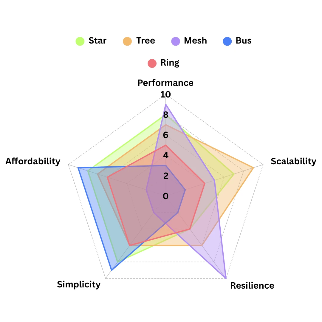
To balance these trade-offs, real-world networks combine multiple topologies into hybrid designs. The impact of topology on each of these characteristics is outlined below:
Network performance
Topology determines how efficiently data moves between endpoints.
- Fewer hops means higher performance: Topologies with direct or near-direct paths reduce latency and congestion, such as star and mesh networks, where devices can reach each other in one or very few hops.
- Shared communication paths reduce throughput: When many devices use the same medium or route, performance degrades under load, such as in bus-like environments where all devices compete for the same bandwidth.
- Sequential paths increase delay: Topologies that pass data through multiple intermediate devices can introduce latency, such as ring networks where traffic travels in order around the loop.
Network scalability
Topology defines how easily a network can grow without major redesign. In general:
- Modular structures scale more effectively: Hierarchical topologies, such as tree topologies, allow incremental expansion without disrupting the whole network, where new branches can be added to extend the network.
- Highly interconnected designs become harder to scale: Each new connection adds complexity and management overhead, as in full-mesh networks, where each new node may require links to many others.
- Shared-medium designs scale poorly: As more devices are added, they compete for limited capacity, and coordination becomes harder, such as in bus networks.
Network resilience
Topology determines how well a network can tolerate failures and maintain connectivity.
- Redundant paths improve fault tolerance: Networks with multiple routes can reroute traffic when a failure occurs, such as a mesh infrastructure where alternative paths maintain connectivity.
- Single points of failure weaken resilience: Topologies that depend on one central node or shared link are more vulnerable, such as star networks without switch redundancy or bus networks with a single backbone.
- Layered designs inherit upstream dependency: In hierarchical networks, failures at higher levels can affect multiple downstream segments, such as a failed core switch disrupting several access layers beneath it.
Network complexity
Topology affects how difficult the network is to design, manage, and troubleshoot.
- Highly interconnected designs increase complexity: More links and routing paths require greater configuration and network monitoring, such as mesh topologies with many interconnections.
- Centralised structures simplify management: Topologies built around clear control points are easier to operate and troubleshoot, such as star networks where the central switch acts as a visible control hub.
- Layered structures improve organisation but add design overhead: Tree topologies make roles clearer across the network, but require careful planning of access, distribution, and core functions.
Network cost
Topology influences both deployment cost and ongoing operational expense.
- More connectivity increases costs: Redundant links and additional hardware raise infrastructure costs, such as in mesh topologies that require many interconnections.
- Centralised designs optimise hardware usage: Star and tree topologies can reduce the amount of cabling or networking equipment needed compared to more redundant alternatives.
- Legacy simplicity can be cheap but inefficient: Bus-style environments use minimal infrastructure, but their performance and fault-tolerance limitations often make them poor value in modern networks.
Network topology – FAQs
Our networking experts answer commonly asked questions regarding network topology:
What is the best network topology for a small business?
There is no single “best” network topology for a small business. Even small networks use a mix of topologies depending on function.
The local network is usually star-shaped around a central business broadband router; WiFi behaves like a shared bus where devices compete for bandwidth, and cloud services operate over distributed tree or mesh-like structures.
What is the difference between network topology and network architecture?
Network topology describes how devices and connections are arranged and how data flows between them.
Network architecture is broader, defining the overall design of the network, including technologies, protocols, control models, and security approaches. Topology is one part of that wider architectural model.
Can a wireless network have a topology?
Yes, wireless networks still have both physical and logical topology, even without fixed cabling between endpoints.
Wireless access points are typically arranged in a star-like layout, while the underlying communication behaves like a shared medium, and mesh WiFi systems introduce multiple paths between nodes for improved resilience.
Which network topology is the most secure?
No topology is inherently the most secure, as security depends more on how traffic is controlled, segmented, and monitored. That said, structured, well-segmented topologies make it easier to enforce access control, visibility, and policy consistently.
Are bus and ring topologies still used today?
Bus and ring topologies are no longer common in most modern business networks due to their limitations in scalability and fault tolerance.
However, ring-based designs still appear in specific environments such as industrial systems and carrier networks where predictable communication or controlled failover behaviour is required.